Battery charger circuit diagram sharing
Publish:BID INTERNATIONAL LTD Time:2024-06-13
Battery charger circuit diagram sharing
1. 2A battery charger circuit diagram using SCR
A simple 2A battery charger circuit designed using SCR (silicon controlled rectifier) TYN612. Here SCR acts as a rectifying element, and the output DC voltage range can be controlled by changing the R7 resistance value. When the target battery is low, no potential flows to the base of the BC547 transistor, and the transistor is off, so the trigger voltage of the SCR reaches the gate terminal, and then the SCR turns on and provides a rectified DC voltage to the battery. When the target battery is fully charged or at a specific threshold charge level, the Q2 transistor BC547 obtains the base potential through R5, R3, and R7, so the transistor turns on and grounds the gate trigger voltage before reaching the SCR gate terminal, then the SCR gets turned off and the battery charging power is blocked.
The AC power is supplied to the step-down transformer, which converts the large AC power into a limited AC power, filters the AC voltage and eliminates noise, and supplies the given voltage to the SCR, where the AC is rectified and the resulting voltage is supplied to the battery charging.
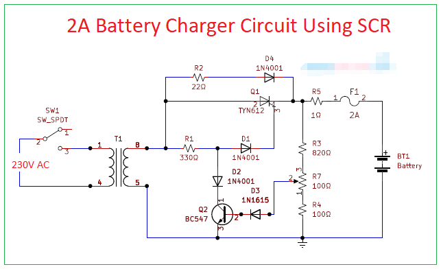
Here the step-down transformer is used to step down 230 or 220V AC to 20V AC (using 2A or 3A transformer). The SCR TYN612 anode terminal is connected to the secondary winding terminal, so it receives the stepped-down AC voltage and converts it into DC power, which is used to charge the target battery.
In order to provide a charging current of 2 amperes, there is no current limiting device after the DC conversion. As we said simple 2A battery charger circuit, the schematic contains few easily available components and simple structure. Q1 thyristor acts as the main rectification element, and Q2 transistor acts as the gate trigger control switch and feedback circuit. The sensitivity of Q2 transistor depends on R7 variable resistor. Here D4 diode acts as a reverse protection element. In order to avoid overcurrent during charging, a fuse is added to the output line.
2. 3.3V battery charger circuit diagram
Here is a 3.3V battery charger circuit designed using Microchip’s MCP16301. The MCP16301 is a highly integrated, high efficiency, fixed frequency, step-down direct current (DC)-DC converter in a popular six-pin SOT-23 package that operates from an input voltage source up to 36V.
Integrated features include a high-side switch, fixed frequency peak current mode control, internal compensation, peak current limit, and overtemperature protection. Minimal external components are required to develop a complete step-down DC-DC converter power supply.
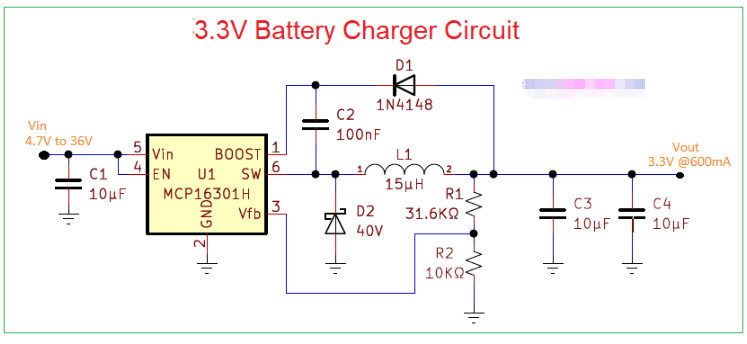
The circuit example has an efficiency of up to 96% with a wide input voltage range (4.5V to 36V) and steps down to 3.3V at 600mA output. The output voltage is currently set to 3.3V and can be adjusted over a wide range of 2V to 15V. The integrated N-channel switch provides low RDSon at 460m. Load operation and efficiency of the MCP16301 at a fixed 5V output.
The EN pin 4 input is used to turn the device on and off. When off, only a few microamps are consumed at the input for power-off and load sharing applications. The input is applied to pin 5, which is the input pin of the IC. Pin 2 is used for grounding. Pin 1 is used for boost capacitor connection, and when the switch is turned on, the boost diode prevents the high voltage of the switch node from feeding back to the output voltage, forcing the switch node to be high. After these connections, the switch output is applied to the inductor and capacitor at the end. The voltage is 3.3V when the output current is 600mA.
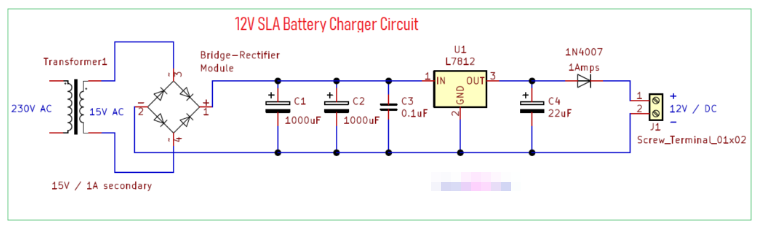
3. 12V SLA Battery Charger Circuit Diagram
SLA (Sealed Lead Acid) batteries are used in different types of applications such as vehicles, inverters, UPS and toys, etc. It can be called Valve Regulated Lead Acid (VRLA) batteries. The 12V SLA battery charger circuit here is designed with a small number of easily available components. This standalone charger circuit provides a constant current 12 volt DC regulated power supply to the SLA battery. There is a 1N4007 diode at the output of this circuit to provide reverse current protection.
This 12 volt SLA battery charger circuit converts 230V AC power to regulated 12 volt DC power through a bridge rectifier and regulator stage. This circuit can charge SLA batteries up to 4.5Ah.
The 2V SLA battery charger circuit is similar to a normal bridge rectifier circuit, starting with a step-down transformer, getting 15Vac from the transformer secondary, rectified to 15V DC through a bridge rectifier module, and after rectification, applying DC power through C1, C2 and C3 filter capacitors to eliminate AC ripple and distortion.
IC 7812 is a positive voltage regulator component with three pins and GND pad, it has different packages, we can choose according to our application and product space, here we use IC 7812 in TO-220 package as a prototype. The first terminal of this IC is the input, the second terminal is ground, and the third terminal is the output terminal. It will provide up to 1A of current and has internal thermal overload protection and short circuit protection.
After the filtering stage, the DC voltage regulated by the positive regulator IC7812 and C4 provides an additional filter to the output DC voltage of the regulator at the end of charging (taken out through the reverse current protection diode 1N4007). This power can then be applied to the SLA battery.
For any questions about power adapters and chargers, you can always consult BID’s sales staff. We believe that as a mature power adapter and charger manufacturer, BID will be able to provide you with professional solutions. Welcome email us via [email protected]
Previous: Which mobile phones are supported by magnetic power banks 2024/08/28
Next:Several misunderstandings about lithium batteries 2024/06/13
Next:Several misunderstandings about lithium batteries 2024/06/13